
Recapping the power supply: the standard first repair.
If vintage audio has one standard repair, this is it. Replacing the electrolytic capacitors in the power supply fixes more sets than any other procedure, and on equipment that's been sitting for decades it's less a repair than a prerequisite.

Replace the power supply electrolytics with parts of the same capacitance and an equal or higher voltage rating, preferably 105°C, low-ESR aluminum electrolytics. On a tube rectifier, don't enlarge the first capacitor past the rectifier's maximum input capacitance (about 10 µF for a 5Y3). Copy the original polarity, deal with the capacitor across the mains before power-up, and bring the set up through a dim bulb tester.
Pick your replacement capacitor
Four quick answers and you’ll have the part to buy and the checks before power-up.
Before your hands go in. Tube equipment can hold enough stored energy to kill you after it has been unplugged for a day. Unplug at the wall, discharge every large capacitor, and measure. See how to discharge a capacitor.
Photograph the values and polarity markings before it comes out.
The common 5Y3 is specified at around 10 µF maximum input capacitance.
Safety first. Tube equipment can hold enough stored energy to kill you after it has been unplugged for a day. Unplug at the wall, discharge every large capacitor, and measure before your hands go in. Work one-handed on anything that might be live. If you are unsure, stop: equipment that has waited forty years will wait another week.
When a recap is the answer
| Symptom | What it suggests |
|---|---|
| Steady hum at mains frequency, worse at volume | Filter capacitors have lost capacitance |
| Broad hiss or fizz behind the audio | High ESR in the filters |
| B+ well below the service figure, sagging under load | Filters no longer smoothing |
| Filaments glow but no sound, or sound arrives very late | Failing filters, or a tired rectifier |
| Bulging, split, or weeping cans | Confirmed: replace them |
| A set in storage for decades | Recap before the first power-up, not after |
That last row matters most. Dried electrolytics can short on first power-up and take the rectifier or the power transformer with them, and the transformer is the part you often can't buy.
B+ is the high-voltage DC rail that feeds the tubes: 90 to 150 V in a table radio, commonly 250 to 450 V in an amplifier. Measure it with the set running and compare it with the service sheet. Then set the meter to AC volts and read the same point: a healthy supply shows a small fraction of a volt to a couple of volts of ripple. Several volts AC on a DC rail means the filters have given up.
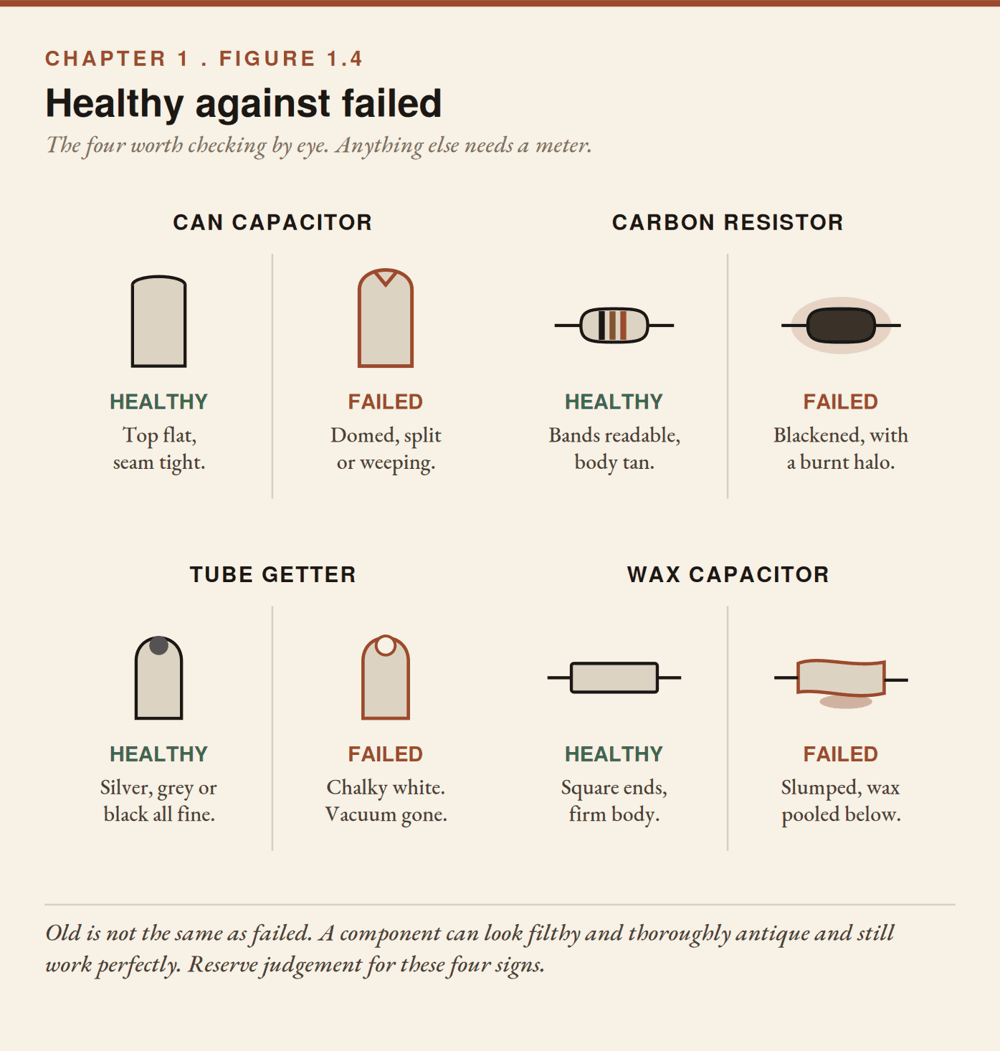
A domed, split, or crusted can is finished. But a capacitor can fail completely and still look perfect, so a clean can proves nothing.
Choosing the replacements
- Capacitance: match the original. The values set the rails' time constants.
- The rectifier limit. On a set with a tube rectifier, the first capacitor after it has a hard limit. The bigger it is, the larger the current surge the rectifier passes. The common 5Y3 is specified at around 10 µF maximum input capacitance, and fitting 47 µF there is a known way to kill rectifiers. Look up yours before increasing that first value. Capacitors further down the chain tolerate modest increases.
- Voltage: equal or higher, never lower. A 450 V position takes a 450 V or 500 V part. This is the most common beginner error, and it fails loudly.
- Temperature: 105°C over 85°C. Electrolytic life roughly doubles for every 10 degrees below the rating, so a 105°C part at 85°C lasts about four times as long.
- Type: aluminum electrolytic, low ESR.
Avoid a film capacitor in a filter position, a non-polarized part where a polarized one belongs, and a physically tiny modern part in place of a large old one, since small parts have low ripple-current ratings and run hot.
Multi-section cans hold several capacitors sharing a common negative. Replace them with a modern replacement can module, restuff the original can with modern parts inside, or mount modern capacitors under the chassis and leave the old can in place as a cosmetic shell. Note what you did for the next person.
Getting the old ones out
- Unplug, pull the tubes and set them aside in order, then discharge and verify with the meter. See how to discharge a capacitor.
- Photograph everything: values, polarity markings, which terminal goes where.
- Note polarity before desoldering. Don't assume the negative goes to chassis: some sets are positive ground. Copy what came out.
- Desolder patiently. Add fresh solder to the old joint first, since its flux makes old solder flow. If a pad starts to lift, stop heating immediately.
- Look at what you uncover. Corroded traces and green residue around a leaked capacitor need cleaning up before the new part goes in.
Fitting the new ones
- Check value, voltage, and polarity on every part before it goes in.
- Trim leads to a sensible length; a heavy part swinging on long leads works its joints loose.
- Use the original clamp or a non-conductive strap for can-style parts.
- Keep electrolytics away from hot resistors and power tubes.
- Point the safety vent where you can see it.
- Check polarity one more time before the covers go on.
The mains side, before first power-up
The capacitor across the mains. Look for a small paper or wax capacitor from one side of the incoming mains to the chassis, or across the two mains wires. When it fails it fails short, which puts the chassis at mains potential. Remove it, or replace it with a safety-rated part: Y-rated from a mains conductor to chassis, X-rated across the two mains conductors. Never an ordinary capacitor, whatever its voltage rating.
Selenium rectifiers look like a stack of metal plates on a bolt. They degrade and pull the B+ down, and a failing one releases toxic fumes: leave the room and ventilate. Replace one with a silicon diode plus a series resistor, then measure the B+ against the service figure to choose the resistor.
The cord. Replace a cracked or hardened rubber cord. On a set with a power transformer, a three-wire cord with the earth bonded to the chassis is a genuine improvement. On a transformerless set, don't do that: use a polarized two-wire plug with the chassis on neutral and the switch in the live.
First power-up
Walk the chassis first: no tools inside, no solder blobs, no leads touching a capacitor, tubes back in the right sockets. Then plug in through a dim bulb tester, a lamp wired in series with the mains: it should glow brightly for a moment as the capacitors charge, then fade. If it stays bright, switch off. Smoke, a burning smell, or loud buzzing means cut the power and find the cause, usually a solder bridge, a reversed capacitor, or a lead that moved.
Once it's up, measure the B+ and the ripple again and compare them with your earlier readings. That comparison proves the job worked.
If the hum is still there
- The rectifier. Substitute a known-good rectifier tube or check the diodes.
- The filter resistors. Carbon resistors between filter stages drift high or go open. Measure them with one leg lifted.
- The grounds. A cracked ground joint or a corroded strap causes hum no part swap will fix.
- Where it enters. Hum at zero volume points upstream of the volume control; hum that grows with volume points before it in the signal path.
Reforming old capacitors slowly on a variac is a preservation technique for originality, not a way to skip buying parts. A variac is not an isolation transformer.
What you need to recap the supply
- Low-ESR 105°C electrolyticsSame capacitance, equal or higher voltage, 105°C, low-ESR aluminum electrolytic. Never a lower voltage.See options on Amazon →
- Digital multimeter, 600 V DCVerify the discharge before your hands go in, then measure the B+ and the ripple before and after.See options on Amazon →
- Dim bulb testerFor the first power-up: it should glow brightly for a moment, then fade. If it stays bright, switch off.See options on Amazon →
- X and Y safety capacitorsFor the capacitor across the mains: Y-rated from a mains conductor to chassis, X-rated across the two mains conductors. Never an ordinary capacitor.See options on Amazon →
- Rosin core solderAdd fresh solder to each old joint before you desolder, since its flux makes old solder flow.See options on Amazon →
These are Amazon links. If you buy through them I earn a small commission, at no extra cost to you.
Run the checks before you plug it in
Get the free Vintage Tube Amp Pre-Power Checklist: six checks to run before an old amp or radio goes anywhere near the wall.
One free PDF, delivered instantly. No spam, unsubscribe anytime.

DIY Vintage Audio Repair
Tube radios, amplifiers, and turntables: parts, safety, recapping, hum, signal path, controls, radio faults, and five full repair walkthroughs.
Read it on Amazon →Should I recap a vintage receiver before turning it on?
Yes, if it has sat for decades. Dried electrolytics can short on first power-up and take the rectifier or the power transformer with them. Recap first, then power up through a dim bulb tester.
Can I use a bigger filter capacitor?
Further down the supply chain, modest increases are fine. The first capacitor after a tube rectifier has a hard limit set by the rectifier, about 10 microfarads for a 5Y3, and exceeding it can kill the rectifier.