
Vintage radio repair: where the signal stops.
A radio is the most rewarding thing to fix, because it's the only one that reaches out and finds something. It's also where beginners waste the most time, almost always by adjusting something they should have left alone. Start with the cheap checks and the safety steps, and most dead radios come back.
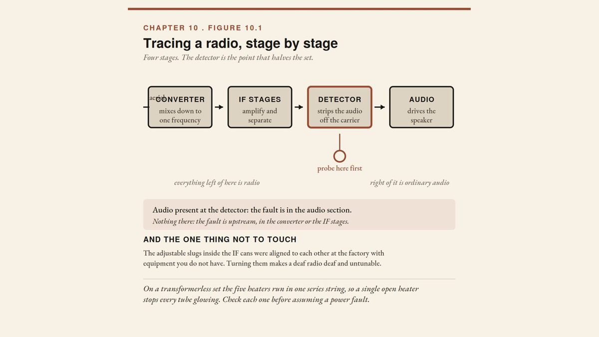
Start with the cheap checks: mains lead and plug, fuse, power switch, connections, then anything visibly damaged. Before power-up, deal with the capacitor across the mains and bring the set up through a dim bulb tester. To find a fault, probe at the detector output: audio there means the fault is in the audio stages, nothing means it's upstream. Capacitors fail first, drifted resistors second, tubes third. Don't touch the slugs in the IF cans.
Safety first. Tube equipment can hold enough stored energy to kill you after it has been unplugged for a day. Unplug at the wall, discharge every large capacitor, and measure before your hands go in. Work one-handed on anything that might be live. If you are unsure, stop: equipment that has waited forty years will wait another week.
The one thing not to touch
Don't turn the slugs in the IF cans, the small adjustable cores inside the shielded metal cans on the chassis. They were aligned to each other at the factory with equipment you don't have, and turning them is how a radio that was merely deaf becomes deaf and untunable. Alignment is a real procedure with real instruments, not a first move.
How a radio is put together
- The converter mixes what the aerial picks up down to one fixed frequency.
- The IF stages amplify that frequency and separate your station from its neighbors. This is where the shielded cans live.
- The detector strips the audio off the radio signal. Everything before it is radio; everything after it is ordinary audio.
- The audio stages amplify that and drive the speaker.
The All-American Five, and its live chassis
Most vintage North American table radios share one design: five tubes, no power transformer.
| Tube | Stage |
|---|---|
| 12BE6 | Converter |
| 12BA6 | IF amplifier |
| 12AV6 or 12AT6 | Detector and first audio |
| 50C5 | Audio output |
| 35W4 | Rectifier |
The leading digits are heater voltages: 12 + 12 + 12 + 50 + 35 is about 121 volts, close to line voltage, which is why there's no transformer. It also means the chassis connects directly to one side of the mains and can sit at full mains potential depending on which way the plug goes in, while looking exactly the same. Work on these unplugged wherever possible. A live measurement needs an isolation transformer, and even then the chassis and circuit can still shock you.
These sets very often have a capacitor from the mains to the chassis, and at this age it will short and put the chassis at mains potential. Remove it, or replace it with a Y-rated safety capacitor, before the set is plugged in. Details are in recapping a vintage radio or amp.
Build a dim bulb tester
A dim bulb tester is a mains socket with an incandescent lamp wired in series with the live conductor. Plug the set into it for its first power-up. A short makes the lamp light brightly and take most of the voltage, so almost no current reaches the radio. A healthy set makes it glow briefly and then go dim or dark. Use a 40 or 60 W bulb for small radios and 100 W for a larger amplifier. It has to be a real incandescent bulb: LED and compact fluorescent bulbs don't work for this.
Check the cheap things first
Always the same order: mains lead and plug, fuse, power switch, connectors and contacts, mechanical faults, then anything visibly damaged. Only then start measuring and replacing. A startling share of dead equipment is a blown fuse or a broken mains lead. Replace a fuse with the same type and rating; if the new one blows, the fuse is protecting you from a fault.
| Symptom | Look at |
|---|---|
| Completely dead, no glow anywhere | Mains lead, plug, fuse, switch, or an open heater string |
| Tubes glow, no sound at all | Speaker and its wiring, output stage, or the rectifier |
| Loud hum, little or no station | Filter capacitors |
| Plays but very weak | Tubes, a leaky coupling capacitor, drifted resistors |
| One band dead, others fine | Band switch contacts, or that band's aerial |
| Crackles when you tune | Dirty tuning capacitor wipers |
| Distorted at any volume | A coupling capacitor leaking DC |
| Fades or cuts out when warm | A capacitor or resistor drifting with heat |
On a transformerless set, the heaters are wired in one series string, so a single open heater kills every tube's glow, like an old string of Christmas lights. Check each tube rather than assuming a power fault.
Find where the signal stops
Probe at the detector output first. If audio is there, the fault is in the audio section; if nothing is there, it's upstream in the RF or IF stages. One measurement halves the radio, and two or three more find the stage. A simple audio probe, a capacitor in series with a lead feeding headphones or a small amplifier, costs almost nothing to make. Swapping in a known-good tube, or temporarily bridging a suspect coupling capacitor with a good one, are the fastest confirmations.
What actually fails
- Capacitors. Filter electrolytics in the power supply and paper coupling capacitors in the signal path account for most faults in a radio that's been sitting.
- Resistors. Carbon composition resistors drift high, 10 to 30 percent is ordinary and high values can be off by multiples. Check the ones in bias networks and the B+ dropping chain, power off, one leg lifted. A "weak" tube is often a starved one.
- Tubes, by substitution.
- Solder joints throughout. Cracked, dull, or grainy joints cause intermittents that cost nothing to reflow.
Older sets from the 1930s and early 1940s may have a field-coil speaker that doubles as the supply's choke. An open field coil kills the set, and you can't just swap in a modern speaker.
Find the paperwork
Almost every American radio was documented, and most of it is free online. Sams Photofact folders and Rider's manuals turn up scanned; Nostalgia Air and Radiomuseum hold schematics for a huge share of sets, searchable by model number. The most useful page is the voltage chart, which turns a meter into a diagnostic tool.
Testing it
First power-up through the dim bulb tester on a switched strip you can cut instantly, with a fire extinguisher in reach. Watch and smell for the first thirty seconds. Then tune across the band: strong stations should be strong, weaker ones should come in between, and neighbors shouldn't bleed together. Let it play for an hour, because heat-related faults hide from a five-minute test.
Before any of this, make the capacitors safe: how to discharge a capacitor. To identify the parts you find: resistor color codes and capacitor markings.
What you need to start on a radio
- Dim bulb testerEvery first power-up goes through one: a short lights the lamp brightly instead of reaching the radio.See options on Amazon →
- Incandescent bulbs, 60 to 100 WA 40 or 60 W bulb for small radios, 100 W for an amplifier. It has to be incandescent: LED and compact fluorescent bulbs don’t work.See options on Amazon →
- Digital multimeterFor checking resistors in the bias networks and B+ chain, power off and one leg lifted.See options on Amazon →
- Y-rated safety capacitorReplaces the mains-to-chassis capacitor before the set is plugged in, or remove it.See options on Amazon →
- Fire extinguisherKeep one in reach for the first power-up.See options on Amazon →
- Isolation transformerNeeded for any live measurement on a transformerless set. Even then, the chassis and circuit can still shock you.See options on Amazon →
These are Amazon links. If you buy through them I earn a small commission, at no extra cost to you.
Run the checks before you plug it in
Get the free Vintage Tube Amp Pre-Power Checklist: six checks to run before an old amp or radio goes anywhere near the wall.
One free PDF, delivered instantly. No spam, unsubscribe anytime.
DIY Vintage Audio Repair
Tube radios, amplifiers, and turntables: parts, safety, recapping, hum, signal path, controls, radio faults, and five full repair walkthroughs.
Read it on Amazon →Should I plug in an old radio to see if it works?
No. Deal with the capacitor across the mains first, and power it up through a dim bulb tester. A set that has sat for decades can short on first power-up and damage the rectifier or transformer.
Why are all the tubes dark on my old radio?
On a transformerless set like the All-American Five, the heaters are wired in one series string, so a single open heater kills every tube's glow. Check each tube before assuming a power fault.